In this post we’ll present an example of the drilling program for a horizontal well in the Bakken formation in the North Dakota portion of the Williston Basin. The Bakken is one of the larger unconventional oil development areas in the US. Drilling designs differ by area and by company, and evolve over time as experience is gained and new technologies and capabilities are developed. However, the well we will review here has strong similarities with wells currently being drilled in other unconventional oil areas such as the Permian Basin and parts of the Eagle Ford. The example we'll use is modeled after an actual, recent well plan that was submitted for approval to the state regulatory agency by a large Bakken operator.
An operator is the oil and gas company that designs the well plan, oversees the work program, and hires and pays suppliers and contractors. The term operator is used because there are often other companies that have working interests in the same well but only one company will serve as operator (If you are unfamiliar with the term "working interest," see our earlier post on leasing). When there are multiple working interest owners, they will commonly establish a "Joint Operating Agreement" (JOA) that describes the rights and obligations of the parties, designates one party to be the operator (usually the party with the highest working interest %), describes the operator duties, describes operator cost-charging procedures, and describes the process for the operator to get approvals for work/expenditures from the non-operators. The operator will will get approval for the well from the non-operators using a form called an "Authority for Expenditure" (AFE) and will send the non-operators a monthly "Joint Interest Bill" (JIB) for their share of the costs. This particular well has multiple working interest owners.
Operators utilize suppliers and contractors throughout the drilling process. For example, the drilling rig and crew are hired from a drilling contractor, usually under a day-rate contract whereby they are paid by the day. A wide variety of other suppliers and contractors are needed at various stages of drilling and operators must have sophisticated capabilities to get equipment, materials, supplies and service crews where needed and when needed. The operator commonly only has one representative at the drill site during the drilling phase, called the "Company Man," but other company employees are monitoring progress remotely during drilling and receive a daily drilling report from the drilling contractor.
Well Sections and Drilling Procedures
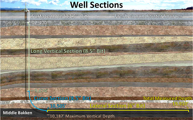
The well in this example will be drilled to the “Middle Bakken” formation, will have a maximum vertical depth of 10,187’, a total measured length of 19,910 feet, and a 9,405’ lateral/horizontal section. It will be drilled in 4 sections: 1) a 13.5" diameter "surface hole," 2) an 8.5" "long vertical section," 3) an 8.5" "curve section," and 4) a 6" "lateral section." Following is a diagram of the well sections (not to scale).
During drilling, a drilling fluid called "mud" will be pumped into the top of the drill string under high pressure. The mud will travel down the drill string, exit through ports in the bit, and will circulate back to the surface through the annular space between the wellbore walls and the outside of the drill pipe. Mud serves several purposes such as cooling and lubricating the bit and carrying cuttings back to the surface. At the surface, cuttings will be removed and the mud will then be recirculated back down the hole. Another critical purpose of mud is to create hydrostatic pressure in the wellbore to counter formation pressure. It is undesirable to have formation fluids invade the wellbore or to have mud invade the formations. Mud density/weight is controlled to try to achieve an effective pressure balance.
At the end of the drill string are the bit and several other tools, collectively called the "bottom hole assembly" (BHA). Common BHA tools for a horizontal well include a mud motor (powered by mud flow and rotates the bit in addition to the drill string rotation), measurement while drilling (MWD) tools that provide information about the bit location, logging while drilling (LWD) tools that provide information about subsurface formations encountered, heavy drill collars to add weight to the bit, and more. The type, size and settings of tools vary for each section.
The curve section requires careful directional drilling in order to land the curve at the correct depth in the target formation at a 90 degree angle. Directional drilling requires: 1) knowing where the bit is at all times, and 2) being able to control the bit direction. There is no GPS device that can signal the bit location from the subsurface so they plot bit movements at intervals to track where the bit must be. For example, if you tell someone exactly where you are standing and then tell them the distance and direction of every move you make, they can plot your movements and keep track of your location. When drilling a well, depth has to be added to that calculation.
In order to directionally drill, the mud motor will be adjusted to have a slight bend (no more than 3 degrees). During the curve section, the bit will only be rotated with the mud motor and the drill string will not be rotated. Drilling can be steered by keeping track of the bit face orientation of the mud motor (the direction in which the bend is pointing). The Measurement While Drilling (MWD) tools constantly track the bit inclination (up-down), aziuth (N-S-E-W), and bit face orientation. This information is constantly relayed back to the rig either through acoustic pulses in the mud or through electromatic signals transmitted to an antenae at the surface. A directional drilling specialist monitors how much more pipe has entered the hole (amount of bit movement) and at certain intervals uses the MWD information to plot/track the bit location. To change the course of the bit, the directional driller will instruct the driller to rotate the drill string a certain number of degrees either clockwise or counter-clockwise (and/or to change the weight on the bit). That partial drill string rotation at the surface will correspondingly change the bit face orientation downhole. This type of drilling is called "sliding."
During the lateral section, the bend in the mud motor will be lessened and the section is mostly drilled while rotating the bit with both the mud motor and the drill string. Sliding may be used occasionally to make course corrections.
Casing
The well will be lined with steel pipe called "casing" at three separate stages during drilling to protect the wellbore and surrounding formations. After enough casing joints are added for the casing string to reach the bottom of the hole, cement is pumped down the casing, out the bottom, and up into the annular space between the casing and the wellbore walls. The cement holds the casing in place and provides an additional protective barrier between the casing and the drilled formations. The diameter of the casing has to be sufficiently smaller than the hole section in which it is installed to leave adequate room for cement on the outside. Once casing has been installed, the next hole section obviously has to be smaller than the inner diameter of that casing because the bit for the next section has to pass through. Following is a diagram of the casing program (not to scale).
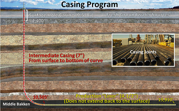
The first string of casing to be installed is "surface casing" extending from the surface to the bottom of the surface hole. State regulations require surface hole drilling to be stopped and surface casing to be installed after the bit passes all fresh groundwater sources in order to prevent groundwater contamination. The maximum depth of groundwater varies by area and the required surface-hole depth is 2,400' at this well location. Surface casing is cemented all the way back to the surface to maximize groundwater protection. The diameter of the surface casing for this well is almost 4" less than the hole diameter, so the cement coating around the casing is about 2" thick.
The next casing string that will be installed is "intermediate casing" extending from the surface to the bottom of the curve section at 10,505'. An intermediate (3rd) casing string is not always needed for horizontal wells but is commonly used in areas where there are zones that could be problematic if left exposed while drilling the lateral section. Intermediate casing does not have to be cemented all the way back to the surface and is cemented to the bottom of the surface casing on this well.
The final casing string that will be installed and cemented is called a “production liner.” The top of the liner will be set or "hung" inside the intermediate casing about 800' from the bottom of that string and will extend to the toe/end of the well. It is called a “production liner” instead of “production casing” because the top does not extend all the way back to the surface. Sometimes production casing is used but the additional pipe adds to costs.
Drilling Procedure Summary
Following is a summary that combines drilling and casing installation in sequence:
- Drill surface hole to 2,400'
- Trip drill string out of hole
- Install surface casing to bottom and cement back to the surface
- Retool Bottom Hole Assembly (BHA) for long-vertical section and trip back into hole
- Drill long vertical section to 9,674'
- Trip out of hole
- Retool BHA for curve section and trip back into hole
- Directionally drill curve section to 10,505' measured depth
- Trip out of hole
- Install intermediate casing from surface to bottom and cement back to bottom of surface casing
- Retool BHA for lateral section and trip back into hole
- Directionally drill lateral to 19,910' measured depth
- Trip out of hole
- Install production liner and set/hang top near bottom of intermediate casing
- Cement production liner to liner top
Batch Drilling
"Batch" drilling on multi-well pads is a common cost-reducing process used today and it alters the procedures shown above. Batch drilling is driven by the fact that regulators require water-based mud (and sometimes air drilling) to be used for surface holes in order to minimize groundwater contamination risks, but operators often prefer to use oil-based mud for the other sections (Oil based mud has better lubricity and doesn't cause shale hydration/swelling like water-based mud). It is a costly and time-consuming process to switch mud types so if multiple wells will be drilled on the same pad, the operator will often drill all the surface holes in sequence with water-based mud and then switch to oil based mud to finish the wells. Sometimes the operator will use a cheaper rig to drill the simple surface holes and use a more-capable rig for the remaining sections.
Our next post will cover how horizontal wells are hydraulically fractured.
If you're interested in learning more about drilling you should watch the trailer for the drilling video we produced. The video clips in the trailer provide a visual overview of rig functions, drilling procedures, casing installation, and equipment, materials and supplies used. The well in the video is a horizontal Barnett shale gas well. You can buy the video on DVD from our website and you can see the trailer here.